Board Display Monitoring
Overview
The Low-Cost Embedded Controller Board Display Monitoring solution is a compact, FPGA-based hardware implementation for real-time system monitoring, control visibility, and diagnostics. Fully integrated to Spring Electronics FPGA System Controller Solution.
Modern mid-range and high-end FPGAs and SoCs require complex power architectures, including strict power sequencing, multiple supply rails, and continuous monitoring of system components such as power regulators, processing subsystems, and high-speed peripherals (e.g., ComEx modules, NVIDIA modules, JESD ADCs/DACs, FPGA PS, CPUs and …).
An on-board OLED display provides the first and most accessible board-level status interface for end users, manufacturing test, hardware designers, and software developers.
The key differentiator of this design is its fully configurable display architecture, where all display behavior, layout, and content are defined using ASCII text files only, without any HDL modifications.
This enables rapid deployment, simple updates, and seamless integration into existing systems without requiring design changes. Design in target to fit relevantly small NVFPGA responsible for board support.
![]()
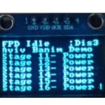
LOGO Display General Display
Integration within System Controller Solution from Spring Electronics
As described in the Overview, modern FPGA and SoC platforms require tight control over power, configuration, and system initialization. These responsibilities are typically handled by a dedicated system controller implemented in a non-volatile FPGA.
The Low-Cost Embedded Controller Board Display Monitoring is designed to operate as a fully integrated block within this Non-Volatile FPGA System Controller, extending its functionality with real-time visibility and control.
In this architecture, the system controller manages critical board-level functions, including:
-
Power sequencing across multiple voltage rails
-
Voltage and current monitoring
-
Board configuration (boot modes, clock selection, mux control)
-
FPGA programming assistance and system bring-up support
The display monitoring block builds directly on top of these capabilities by providing an immediate, on-board interface to system status and diagnostics. Instead of relying on external tools or software access, users can observe system behavior in real time during power-up, operation, and fault conditions.
This integration model aligns with system controller architectures used in advanced FPGA platforms, including solutions implemented in AMD Xilinx Versal Adaptive SoC system controller, where centralized control and monitoring are essential for reliable system operation.
By embedding display monitoring within the system controller, the solution provides:
-
Instant board-level visibility from the earliest power-up stages
-
Simplified manufacturing test and validation processes
-
Faster system bring-up and debug cycles
-
Reduced dependency on external debug interfaces
-
A consistent and unified control and monitoring framework
Key Features
-
Zero-HDL Configuration Flow
Configure displays, register mapping, and behavior entirely via ASCII text files—no FPGA recompilation required -
Real-Time Board Visibility
Instant on-board status for power, system state, and diagnostics from the earliest power-up stage -
Integrated System Controller Solution
Fully embedded within a Non-Volatile FPGA system controller handling power sequencing, monitoring, and configuration -
Low-Cost, Hardware-Only Implementation
Pure FPGA logic design with no CPU dependency, enabling deterministic and reliable operation -
Rapid Customization & Deployment
Python-based tools generate configuration files, enabling fast updates and flexible system adaptation -
Scalable Multi-Display Support
Supports multiple OLED displays with independent content and layout control -
Cross-Platform FPGA Compatibility
Portable across AMD/Xilinx, Intel (Altera), Lattice, and Microchip FPGA families -
Enhanced Debug & Manufacturing Efficiency
Reduces reliance on external tools by providing immediate visual feedback during bring-up, test, and field operation -
Aligned with Modern System Architectures
Follows system controller design principles used in advanced FPGA platforms while maintaining simplicity and cost efficiency
System Block Diagrams
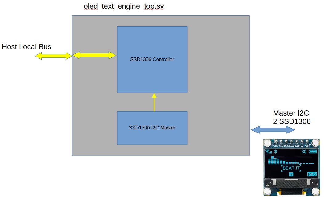
Key Advantages
-
Ultra-low FPGA resource utilization – optimized for cost-sensitive designs
-
Fully hardware-based implementation – deterministic, fast, and reliable
-
Cross-platform support: Xilinx, Lattice, Intel (Altera), Microchip
-
Scalable architecture supporting multiple displays and system expansion
Zero-HDL Display Configuration (Core Advantage)
All display configuration are performed using ASCII text files only:
-
Define display pages, layouts, and content using simple text files
-
Map user registers dynamically to display positions
-
Modify system behavior without any HDL changes
-
Python-based tools generate all required initialization files
This approach significantly reduces development time and allows non-FPGA developers to control system display behavior.
System Capabilities
-
Support for up to 8 OLED displays (SSD1306, 128×64)
-
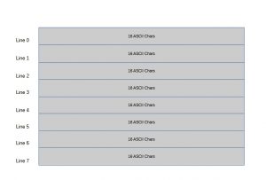
Each display supports 8 lines of 16 ASCII characters
-
Each character can be mapped to a user-defined register
-
Up to 128 user registers supported
-
Up to 8 state machine status indicators
-
Built-in power-up “Logo Page” with scrolling capability
Design Concept
Unlike traditional FPGA-based display controllers that require HDL modifications for every change, this solution separates:
Hardware (FPGA logic) – fixed, optimized, and reusable
Configuration (display behavior) – fully controlled via ASCII text files
This separation enables:
-
Rapid updates in the field
-
Simplified maintenance
-
Reduced design risk
-
Faster iteration cycles
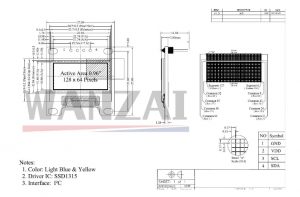
Display Screen Setup – SSD1306 128 x 64 Pixels
OLED Display Configuration
The system uses SSD1306-based 128×64 OLED displays.
Each display:
-
Is divided into 8 text lines
-
Each line supports 16 ASCII characters
-
Supports dynamic content driven by user registers
Display behavior, including layout and content, is fully defined using ASCII configuration files.
ASCII Configuration Files
Two primary ASCII files control the system:
init_ascii_text_memory.txt
Defines display layout, static text, and structure
ssd_user_reg_dpr_init.txt
Defines user register initialization and dynamic mapping
These files are generated using a Python-based tool-chain, enabling fast configuration and updates without HDL changes.
User Configuration Flow
-
Define display layout and content using ASCII text files
-
Define user registers and mapping
-
Run the Python generation tool
-
Generate initialization files
-
Load into FPGA memory
No HDL modification, synthesis, or implementation is required for display updates.
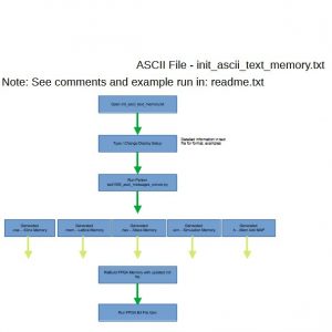
ASCII File – init_ascii_text_memory.txt
/ Inject Register opcode: “:” Start and flag user register
// Inject must be in 8 char
// Format after :# (opcodes based on ascii chars), we have 8 ascii chars after the flag
// <Reg Select7><Reg Select6><Reg Select5><Reg Select4><Reg Select3><Reg Select2><Reg Select1><Reg Select0><OpCode MSB><OpCode MID><OpCode LSB><:><4 ASCII Chars>
// user have max 8 chars for user print in line – used for registers live voltage, current and more
// Valid OpCodes are Opcodes from code U+0030 (0) to U+0039 (9)
// <OpCode> – Can be only numbers 0 to 9 ascii char
// U+0030 (0)
// U+0031 (1)
// U+0032 (2) and so on up to U+0039 (9)
// U+0041 (A) to U+0046 (F)
// Note!!
// It is user responsibility to make sure the OpCode ASCII codes used are legal! so when run Phyton, make sure you read
// the notes from Phyton and no errors in suer registers line
//////////////////////////////////////////////////////////////////////////////////
// initial begin
//////////////////////////////////////////////////////////////////////////////////
// Index line 7 is for the bottom of the LCD
// 5432109876543210
//////////////////////////////////////////////////////////////////////////////////
// LOGO Display – Display No 0
//////////////////////////////////////////////////////////////////////////////////
// initial begin – Line 7:
” springelec.com “
// Line 6:
“++ Design ++”
// Line 5:
“++ ++”
// Line 4:
“+ Electronics +”
// Line 3:
“++ ++”
// Line 2:
“++ Spring ++”
// Line 1:
“++ ++”
// Line 0:
“ABCDEFAB000:Dis0”
Typical Applications
-
Board-level monitoring and diagnostics
-
Power system monitoring and control
-
Industrial and embedded system status display
-
FPGA-based systems requiring low-latency human interface
-
Lab bring-up, validation, and debugging environments
OLED Mechanics